|
Our solution
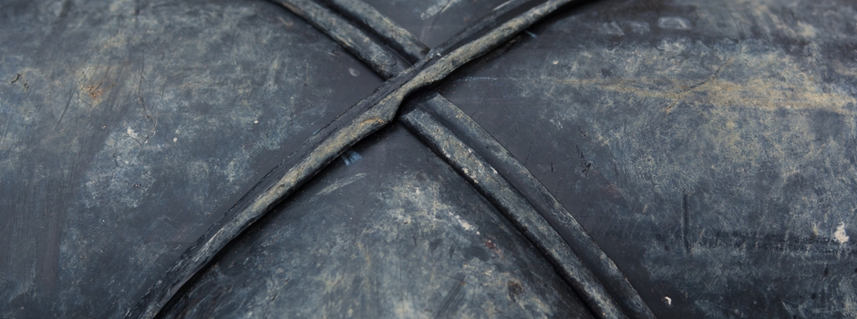
There were 2 welds to consider, running around an outer
circumference and an inner one. The tank was asymmetric
so we could not model a segment of it. Our consultants
built an FEA model of the tank and
base using shell elements and loaded them to understand
the gross stresses and deflections. This allowed us to
chose a plane to cut the tank, where there were no deflections
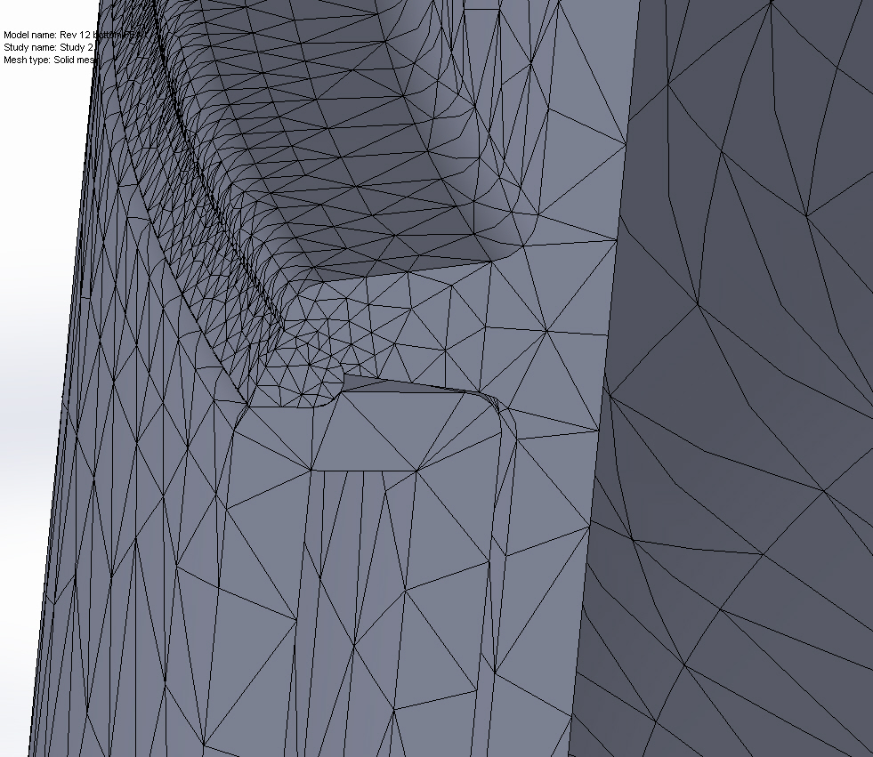
and build a more detailed FEA model
of the remaining portion using solid elements.
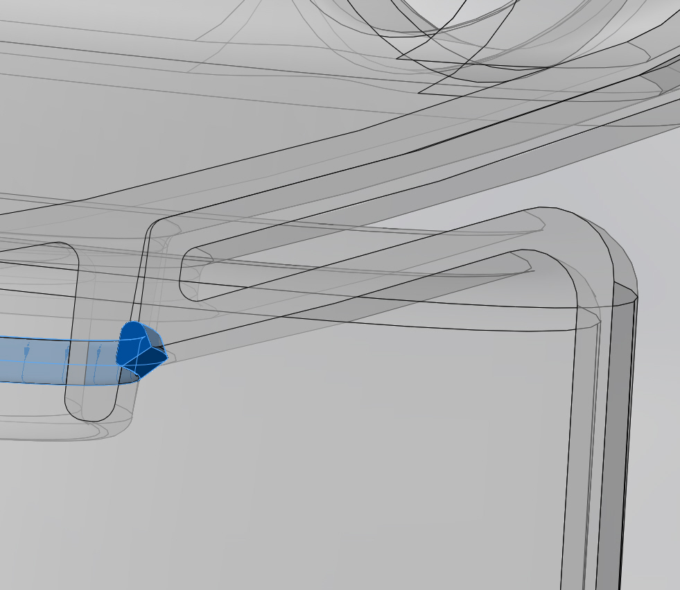
Having taken advice from the supplier of the weld gun,
our consultants modelled the weld bead, including its
outer face and its typical penetration into the melted
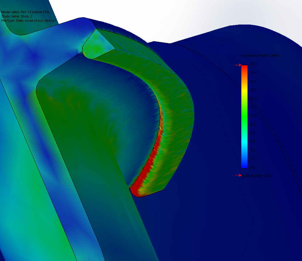
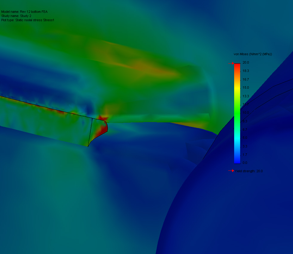
surfaces below. We predicted the residual stresses from
the welding process using a thermal boundary condition
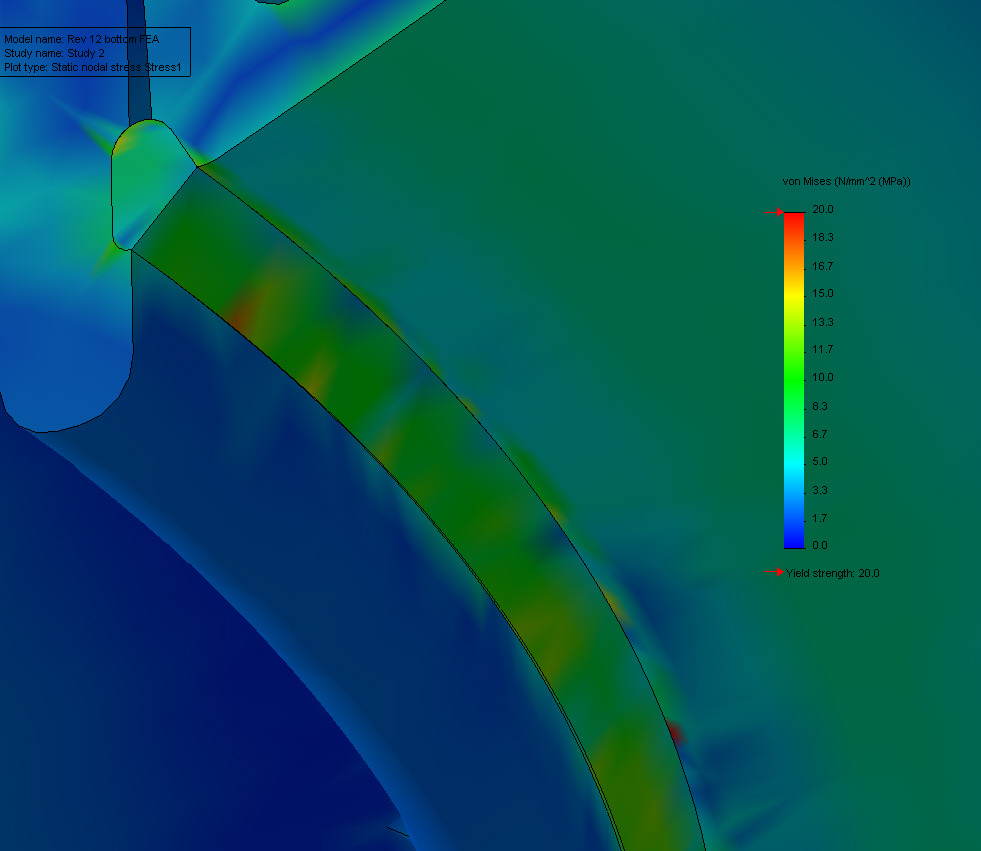
on the weld. Finally, the loads on the tank were added
in, so the weld stresses could be predicted. The results
showed that the weld stresses may lead to long-term cracking
and failure. The design loads on the tank were then limited
to a safe level, to give adequate performance from the
welded joint.
|